Daytime tracking and backtracking
Site-specific backtracking is standard and reduces row-to-row shading when the sun is low. Terrain-following backtracking can be added where the site and control strategy require it.

Single-axis solar tracker
The Track-Max120 combines a structural steel platform, 1P portrait module arrangement, slew-drive actuation and independent closed-loop control. Lumax Energy designs, engineers and manufactures each system for ground-mounted solar PV projects across Africa, from smaller site-specific installations to large utility-scale facilities.
From smaller sites to utility scale
Not every tracker opportunity is a multi-megawatt utility plant. Lumax can engineer smaller tracker structures where the energy and commercial case supports tracking, then scale the same project-specific approach to large utility developments.
Every system is developed from the project location, energy objectives, module selection, layout, terrain, wind requirements, geotechnical conditions, corrosion environment, foundation strategy and construction methodology. Lumax can also provide installation, installation supervision and commissioning according to the agreed project scope.
Locally supported tracker engineering, sized to the site and the energy case.
Benefit from site-wide structural optimisation, manufacturing scale, installation planning and commissioning support.
Table length, row geometry, supports, foundations, controls and delivery scope are adapted to each project rather than forcing every site into one standard table.
Commercial selection
A single-axis tracker rotates the PV modules through the day so that the array remains better aligned with the sun’s path. On a suitable site, tracking can increase energy capture compared with a fixed-tilt structure and improve the timing of generation across the day. The benefit depends on irradiance, module technology, row spacing, GCR, backtracking strategy, terrain, availability and the fixed-tilt baseline, so Lumax does not apply a universal percentage uplift.
Typical values
These values describe typical Lumax tracker projects. Special requirements can be assessed through project-specific engineering.
SAT-01 · Track-Max120
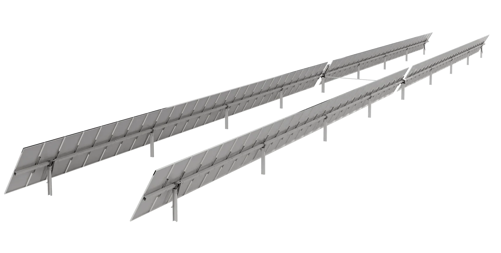
Continuous-Row Operating Principle
The module table rotates around a north–south axis while the supports remain fixed.

Module arrangement
1P portrait
Tracker table length
Typically designed up to approximately 100 m
Total motion
Typically 110° total; up to 120° by special request, subject to project design
Ground coverage ratio
Typically 30% to 50%
Terrain gradients
Typically up to 15% north-south and east-west, subject to site assessment
Drive method
Slew drive
Primary structure
Structural steel
Values are typical and project-specific, not universal maximums.
| Design input | Typical project basis |
|---|---|
| Module arrangement | 1P portrait |
| Tracker table length | Typically designed up to approximately 100 m |
| Total motion | Typically 110° total; up to 120° by special request, subject to project design |
| Ground coverage ratio | Typically 30% to 50% |
| Terrain gradients | Typically up to 15% north-south and east-west, subject to site assessment |
| Drive method | Slew drive |
| Primary structure | Structural steel |
How the tracker works
The module tables rotate around a horizontal north–south axis using a slew-drive mechanism. Independent closed-loop control combines feedback with an astronomical tracking algorithm with seasonal adjustment, so the tracker follows the required daily angle profile.
Site-specific backtracking is standard and reduces row-to-row shading when the sun is low. Terrain-following backtracking can be added where the site and control strategy require it.
At night the tables return to a predefined stow position as a standard operating feature. The final position is set for the project.
Wind speed is monitored through an anemometer input. At the site-specific trigger, the control system moves the tracker to its defined protective position.
SAT-03 · Track-Max120
Backtracking Across Adjacent Rows
At low sun, backtracking adjusts table position to limit row-to-row shading. Switch between the matched views.
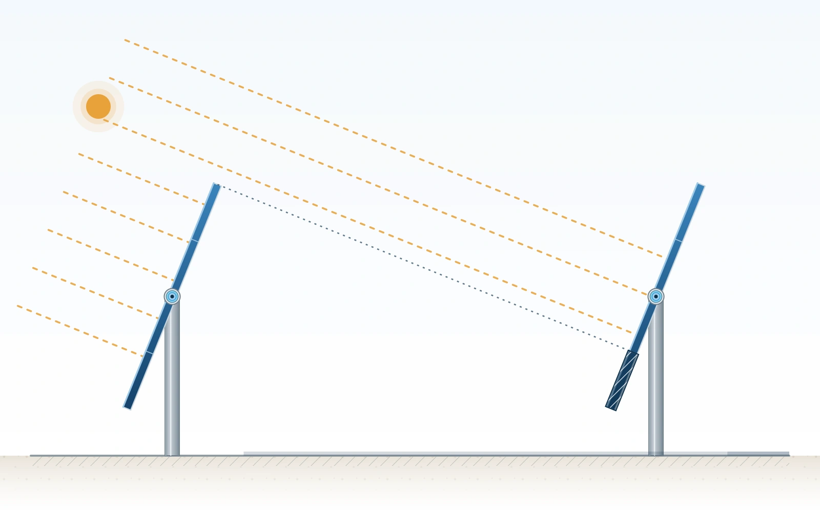
Direct alignment: illustrative example. Direct alignment produces shading on the adjacent row.
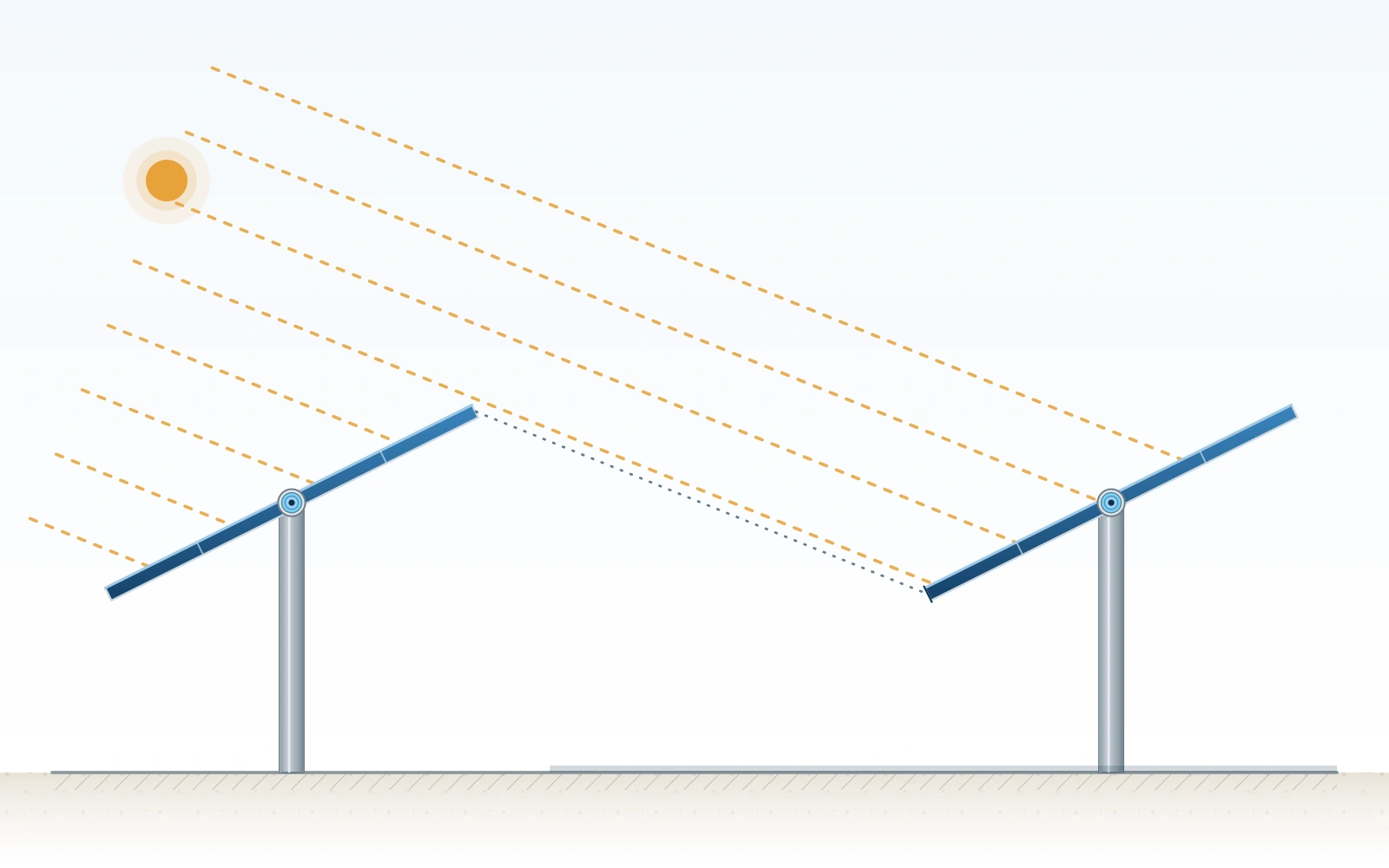
Backtracking: illustrative example. A changed table angle limits shading between the rows.
Plant architecture
Lumax integrates project-appropriate controller hardware and tracking software with the mechanical tracker platform. Commissioning of the agreed tracker functions is included as a standard part of the Lumax tracker supply scope.
Controller power, gateways, the anemometer input, communication topology, event logging and interfaces are defined during project engineering.
Communication methods are selected according to the plant architecture. The method is confirmed during project engineering.
Independently controlled tables and linked master and slave tables are configured during engineering. The selected method depends on controller arrangement, layout, distances, plant infrastructure and integration requirements.
Integration into the plant SCADA system is outside the standard Lumax scope and is coordinated with the EPC, controls contractor or plant integrator.
SCADA interface responsibilities and plant integration requirements are agreed during project development. Basic control-system training and installation training can be provided on request.
One connected design problem
Tracker structures combine static structural design with controlled movement and protective operating logic. Location, wind actions, table geometry, module selection, supports, foundations and stow strategy are assessed as one design problem.
Structural wind design considers SANS 10160, including SANS 10160-3 for wind actions. Development has included full-scale wind-tunnel testing with the CSIR. Operating and stow thresholds are project-specific; no site-independent wind speed should be inferred from this page. IEC 62817 work is in progress; no IEC 62817 certification is claimed.
The topographical survey and preliminary layout inform table arrangement, GCR, row lengths and support strategy. Typical projects accommodate gradients up to 15% north-south and east-west, subject to detailed engineering.
Lumax designs to the corrosion category supplied for the project. Options can include pre-galvanised steel, hot-dip galvanising to ISO 1461 and ZMA-coated steel, depending on the client-supplied corrosion category and project specification. The final steel grade, coating system, thickness, interfaces and inspection requirements are selected for the actual exposure. A coating name alone does not replace a project-specific durability assessment.
The 1P portrait platform is designed around the client’s selected module. Lumax reviews dimensions, mass, frame and clamp zones and obtains project-specific compatibility approval from the module manufacturer. Bifacial modules can be accommodated, subject to the module, layout and project design.
Foundation selection
The foundation is part of the tracker system. It is selected from the geotechnical conditions, structural reactions, construction method, corrosion exposure, access and programme. Final type, section, depth and installation requirements are confirmed through project-specific engineering.
Shown: a driven support.
A common foundation route, selected from the geotechnical conditions, structural reactions, construction method, corrosion exposure, access and programme.
Driven piles are a common foundation route where the ground conditions and structural reactions suit them. On-site pull-out testing is recommended for every driven-pile project, mandatory where Lumax provides structural sign-off, and must be completed before procurement because results may change the required pile length and foundation design.
Shown: a support within concrete.
A common foundation route, selected from the geotechnical conditions, structural reactions, construction method, corrosion exposure, access and programme.
Drill-and-concrete is a common foundation route. Its suitability, and the final foundation design, are confirmed through project-specific engineering.
Shown: rammed support and engineered pad or cap.
A project-specific alternative where the ground conditions or structural solution require it.
Direct-rammed supports with a pad or cap are a project-specific alternative, assessed where the ground conditions or structural solution require them.
Delivery and lifecycle
Lumax can undertake tracker installation, provide installation supervision or support the appointed construction team according to the project scope. Where Lumax installs its own tracker, the engineering, manufacturing, installation and commissioning teams work from one controlled design basis.
Commissioning is included as a standard part of the Lumax tracker supply scope and covers the agreed mechanical movement, controls and operating functions. Technical support is available during project development, construction, commissioning and operation. Plant SCADA integration remains outside the standard Lumax scope.


Low-maintenance mechanical design
The bearing arrangement uses self-lubricating polymer bushings, reducing a recurring maintenance activity across large tracker fields. A two-piece bearing housing supports inspection and component access. Lumax supplies a project O&M manual defining inspection, preventative-maintenance and operating requirements.
South African capability
The Track-Max120 brings structural engineering, local manufacturing, installation capability and technical support together within one South African organisation.
Up to 95%
local content may be achievable
Depending on project scope, sourcing strategy, client requirements and applicable calculation rules or exemptions. The final value is calculated for the specific project and is not a guaranteed percentage for every supply.
Project delivery
Seven stages from first definition to ongoing technical support.
Confirm the site, capacity, module, energy objective, layout basis and commercial requirements.
Assess topography, wind, geotechnical data, corrosion category, GCR and construction constraints.
Establish tracker geometry, table length, supports, foundations, controls and communication method.
Complete the structural design, module compatibility route, wind strategy and required site testing.
Produce controlled components and project documentation to the approved design basis.
Install or support installation, verify mechanical movement and commission the agreed tracker functions.
Provide the project O&M manual, training where included and ongoing technical support.
Start a project
A project can enter concept selection before every technical input is complete. Lumax will use the information available, state the assumptions and identify what is still required before final design.
On the enquiry form, select Single Axis Trackers and summarise the inputs listed here that are already available.
Project and module
Location, capacity, programme, module manufacturer, model, datasheet and procurement status.
Layout and yield
Preliminary layout, coordinates, topographical survey, target GCR and the tracker versus fixed-tilt comparison basis.
Ground and environment
Available geotechnical information, proposed foundation strategy, wind criteria and corrosion category.
Controls and interfaces
Control architecture, anemometer requirements, communication preferences and SCADA interface responsibilities.
Construction
Construction methodology, access constraints and installation scope.
Commercial requirements
Local-content, tender and project documentation requirements.
Download the existing Single-Axis Tracker reference data sheet. Where its values differ from this page, this page and project-specific engineering take precedence. Project-specific documentation can include drawings, calculations, installation information, commissioning records and the O&M manual according to the agreed scope.
Technical questions
Short answers to common tracker questions. Project-specific engineering confirms the final design.
No. Lumax can engineer tracker systems for smaller site-specific solar PV projects as well as large utility-scale facilities. Suitability is assessed from the energy objectives, layout, module, terrain, wind, foundations, controls and commercial requirements.
There is no universal uplift. Irradiance, module technology, GCR, backtracking, terrain, availability and the fixed-tilt baseline all affect the result. The project energy model should determine the expected benefit.
Typically 110° total. Up to 120° is available by special request, subject to project design. Final tracking angles are project-specific.
Typical projects can accommodate gradients up to 15% in both principal directions, subject to detailed assessment of local grade changes, foundations, row geometry and energy impact.
Wind speed is monitored through an anemometer. At the site-specific trigger, the tracker moves to the defined protective position. The trigger and stow logic are confirmed for each project.
Driven piles and drill-and-concrete foundations are common. Direct-rammed supports with a pad or cap can also be assessed as a project-specific alternative.
On-site pull-out testing is recommended for every driven-pile tracker project. It is mandatory where Lumax provides structural sign-off and must be completed before procurement, because the results may change the required pile length and foundation design.
Communication methods are selected according to the plant architecture and confirmed during project engineering. Plant SCADA integration is outside the standard Lumax scope.
Yes. Commissioning is included as a standard part of the Lumax tracker supply scope and covers the agreed mechanical movement, controls and operating functions.
No routine bearing lubrication is required. The system uses self-lubricating polymer bushings, with inspection and maintenance requirements defined in the project O&M manual.
Yes, subject to project-specific module review, layout design and compatibility approval from the module manufacturer.
Local content of up to 95% may be achievable, depending on the project scope, sourcing strategy, client requirements and applicable calculation rules or exemptions. The final value is calculated for the specific project.
Share the available site, module, layout and programme inputs for a structural and technical discussion with Lumax engineering.