Lumax fixed-tilt solar structures

Ground Mount Solar Structures Engineered for the Site

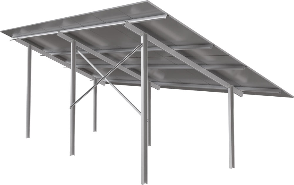
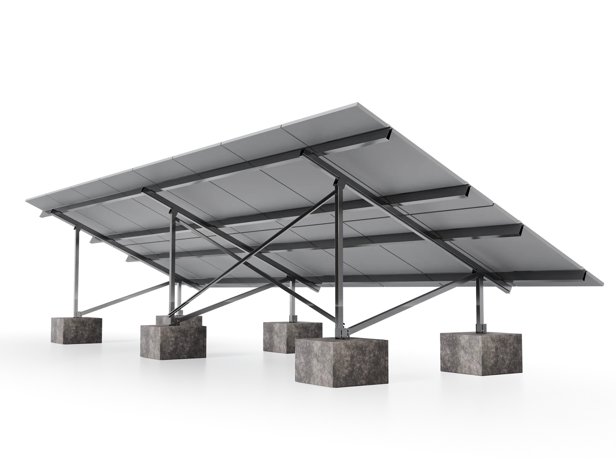
Lumax Energy designs, engineers and manufactures fixed-tilt Ground Mount structures for commercial, industrial and utility-scale solar projects across Africa.

The current Lumax Ground Mount range is built around two structural platforms: AluCore and SteelCore. Both are available as standard pre-engineered kits for suitable projects and as project-specific engineered structures.

The platform is selected together with the module configuration and foundation method. Wind region, terrain, geotechnical conditions, corrosion exposure, module geometry, project scale, installation methodology and commercial objectives are assessed as one design problem.

Start With the Site, Not the Material

Aluminium and steel each bring distinct strengths to the structure. Each platform creates different opportunities for corrosion management, component design, support spacing, handling, fabrication and project optimisation. Lumax therefore recommends AluCore or SteelCore only after reviewing the conditions that drive the complete installed structure.

How Lumax Selects Between AluCore and SteelCore

The starting point is the project requirement, not a predetermined product. Lumax compares the following inputs before recommending the structural platform:

  1. Corrosion exposure

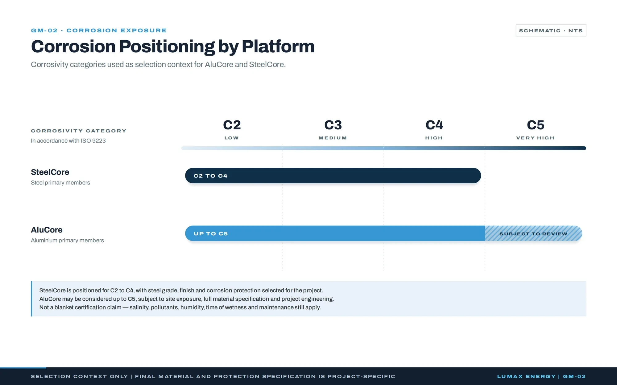
    SteelCore is positioned for C2 to C4. AluCore can be considered for applications up to C5, subject to project review.

    • AluCore
    • SteelCore
  2. Structural layout

    Module dimensions, table geometry, tilt, support spacing and loading determine which member arrangement is efficient.

  3. Support span

    AluCore normally uses the R112 profile for spans up to 4 m where engineering permits. R90 is the less common AluCore option where support spacing is 3 m or less. SteelCore supports spans up to 4 m, subject to loading and project engineering.

    • AluCore
    • SteelCore
  4. Foundation strategy

    Direct-driven piles, pre-drilled and driven piles, drill-and-concrete, ground screws and conventional concrete can be assessed with either platform. The foundation method is selected for the site, not used as a separate product identity.

  5. Construction method

    Access, available plant, installation sequence, handling, assembly and programme can materially affect the most practical solution.

  6. Commercial outcome

    The complete structure, foundations, material utilisation, manufacturing and site installation are considered together. The lowest-cost member is not necessarily the lowest-cost installed solution.

Standard Kits and Custom-Engineered Structures

Lumax compares standard and custom routes before recommending the better project outcome.

GM-06 · Commercial design route

Project inputs

  • Location and wind region
  • Module and configuration
  • Capacity and layout
  • Loading and site conditions

Within the approved standard design envelope?

Yes

Common configurations

Standard pre-engineered kits

Standard AluCore and SteelCore kits are available for common configurations, subject to availability and the project falling within the approved design envelope. Because the structural engineering and standard drawings are already established, these kits can shorten the route from enquiry to quotation and supply.

For projects of approximately 1 MW and smaller, a standard kit will often be the most practical commercial route. Larger projects may still use standard kits, but scale creates greater opportunity to optimise table length, support spacing, member sizes, connections, foundations, material utilisation and the overall layout.

No · or scale justifies optimisation

Project optimisation

Custom-engineered structures

For projects above approximately 1 MW, a custom-engineered structure is generally more cost-effective because even modest project-specific efficiencies can be repeated across a large number of tables and foundations. Lumax will compare the standard and custom routes before recommending the better project outcome.

Scale creates the opportunity to optimise

  • Table length
  • Support spacing
  • Member sizes
  • Connections
  • Foundations
  • Material use
  • Overall layout

Larger projects may still use standard kits. Lumax compares both routes before recommending the better project outcome. The lowest-cost member is not necessarily the lowest-cost installed solution.

Illustrative selection logic · Final route is confirmed per projectLumax Energy | GM-06

GM-01 · Confirmed fixed-tilt arrangements

Confirmed Fixed-Tilt Configurations

End elevations of the module arrangements supported by AluCore and SteelCore.

Schematic · Not to scale

See what information helps Lumax assess each arrangement. A preliminary layout or preferred tilt is useful if available; you do not need a final design to start.

2P Portrait

Two modules in portrait

Illustrative end elevation of two portrait modules on one inclined module plane.

Tilt range10° to 25°

2P Portrait

Preparing a 2P layout

Share the module datasheet, preliminary layout and preferred tilt, if known. Lumax reviews module dimensions, loading and site conditions to establish the final table geometry and tilt.

3P Portrait

Three modules in portrait

Illustrative end elevation of three portrait modules on one inclined module plane.

Tilt options10° or 15°

3P Portrait

Preparing a 3P layout

If known, indicate whether the preliminary layout uses 10° or 15° and share the module datasheet. These are two design options; Lumax confirms the final arrangement against module dimensions, loading and site conditions.

East-West / 4P

Two east, two west

EastWest

Tilt range10° to 15°

East-West / 4P

Preparing an East-West layout

Show the intended east- and west-facing module arrangement in the preliminary layout, if available, and share the module datasheet. Lumax reviews module dimensions, loading and site conditions before confirming the final geometry.

Wind, Corrosion and Site Engineering

The platform, geometry and foundations are developed together. No isolated material choice replaces the project engineering basis.

Wind region

Designed for the Project Wind Region

Wind loading affects member sizes, support spacing, connections and foundation reactions. Standard designs are available for SANS wind regions of 36 m/s and 44 m/s.

Lumax uses the project location and available design information to determine whether a standard design is appropriate. Where the project falls outside the standard design envelope, or where project requirements demand a different basis, Lumax develops a project-specific engineered solution. For projects outside South Africa, the applicable national and project design requirements are confirmed as part of the engineering scope.

Exposure

Corrosion Exposure Is a Design Input

C2, C3, C4 and C5 are environmental corrosivity classifications. ISO 9223 provides a system for classifying atmospheric corrosivity, while ISO 12944 uses environmental classifications as an important input when corrosion-protection systems for steel structures are selected.

Project authority

Categories inform the specification

On the Lumax website, these categories are used as selection context, not as blanket product certification. SteelCore is positioned for C2 to C4 exposure with a project-appropriate corrosion-protection system. AluCore may be considered for applications up to C5, subject to the full environmental, material and engineering review. Local salinity, pollutants, humidity, time of wetness, maintenance expectations and the detailed component specification remain relevant.

GM-02 · Corrosion exposure

Corrosion Positioning by Platform

Corrosivity categories used as selection context for AluCore and SteelCore.

Corrosion positioning by platform: SteelCore positioned for C2 to C4; AluCore may be considered up to C5, subject to review. Selection context only, not a blanket certification.
Selection context only · Final material and protection specification is project-specificLumax Energy | GM-02

Foundation Selection Starts With the Ground

The mounting structure and foundations act as one structural system. Soil behaviour, rock or refusal depth, groundwater, erosion risk, structural reactions, project scale, construction equipment and programme all influence the preferred foundation method.

Illustrative foundation routes, not supplied member, connection, anchor or reinforcement details. Final type, section, depth and installation are project-engineered. Not for construction.

Shown: a driven support.

Direct-driven piles

Normally preferred at scale where ground allows reliable installation.

01 · Direct-driven piles

When is direct driving considered?

Normally preferred for larger projects where ground conditions allow reliable installation. Direct driving is generally the fastest and most cost-effective method at scale, but it requires specialist piling equipment and verified site performance.

Shown: pre-drilling through a harder ground layer.

Pre-drilled and driven piles

Where harder layers or local refusal hinder direct driving.

02 · Pre-drilled and driven piles

When does pre-drilling help?

Used where direct driving is difficult but a driven-pile solution remains practical. Pre-drilling assists installation through harder layers or local refusal conditions while retaining the pile-based foundation approach.

Shown: support within concrete.

Drill-and-concrete

Where effective pile driving is not practical.

03 · Drill-and-concrete

When is drill-and-concrete considered?

Used where effective pile driving is not practical, particularly on larger sites where ground conditions require drilled holes and a concreted pile or post arrangement.

Shown: an illustrative helical ground screw.

Ground screws

An alternative for selected soils and access, usually at a higher cost.

04 · Ground screws

When are ground screws considered?

Foundation selection follows the site conditions and project design. Direct-driven piles are normally preferred for larger installations where ground permits. Ground screws provide an alternative where appropriate, usually at a higher cost.

Shown: an illustrative concrete pad and stub arrangement.

Conventional concrete foundations

Normally considered for smaller sites or suitable standard-kit projects.

05 · Conventional concrete foundations

When are concrete foundations considered?

Normally considered for smaller sites and suitable standard-kit projects where mobilising specialist piling equipment would not be commercially justified. The civil foundation and structural anchoring scope must be clearly defined for the project.

Illustrative foundation concepts · Final geometry is project-specific · Not for constructionLumax Energy | GM-03

Mandatory pull-out testing for direct-driven piles

Whenever direct-driven piles are selected, on-site pull-out testing is mandatory for every project and must be completed before manufacture. Testing confirms the required pile embedment and verifies the foundation assumptions used in the structural design.

What Lumax Can Do Before Geotechnical Information Is Available

A project can enter the quotation and concept-selection process before a complete geotechnical report is available. Using the project location, module information, preliminary layout, capacity, tilt and declared assumptions, Lumax can assess the likely platform, configuration, standard-kit suitability and preliminary foundation routes.

The selection is provisional until the ground is verified

The proposal will identify the assumptions and information still required. As geotechnical and site data becomes available, Lumax can refine the foundation strategy, support spacing and project-specific design.

From Project Inputs to Manufactured Structure

Six stages from first project definition to quality-controlled manufacture.

GM-08 · Project delivery

  1. Define

    Location, capacity, module, preliminary layout, tilt and available technical requirements.

  2. Review the site

    Wind region, terrain, corrosion exposure and available geotechnical information.

  3. Select the solution

    AluCore or SteelCore, configuration, standard kit or custom-engineered structure.

  4. Set the foundations

    Method selected around ground behaviour, structural reactions, scale and construction methodology.

  5. Optimise

    Member sizes, support spacing, connections, foundations, material utilisation and constructability.

  6. Detail and manufacture

    Approved drawings, quality-controlled production, packing and project support in accordance with the agreed scope.

Illustrative delivery process · Scope is confirmed in the project agreementLumax Energy | GM-08

What We Need to Design and Quote

You do not need every input before speaking to Lumax. Send the information currently available and identify what is still outstanding.

  1. Project location and country
  2. Approximate project capacity in MW
  3. PV module manufacturer, model and datasheet
  4. Preliminary site plan, array layout or available coordinates
  5. Preferred configuration and tilt, where known
  6. Available topographical and geotechnical information
  7. Corrosion or environmental requirements stated by the client
  8. Tender, employer, grid or project technical requirements
  9. Target programme, delivery phasing and any installation constraints
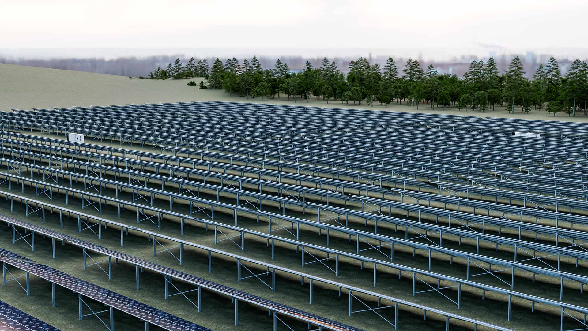
Rows of Lumax fixed-tilt Ground Mount structures across a solar site
Lumax fixed-tilt Ground Mount structures

Ground Mount Frequently Asked Questions

Should a project start with AluCore or SteelCore?

Start with the site and project requirements. Lumax compares corrosion exposure, loading, layout, foundations, construction and commercial outcomes before recommending a platform.

Is a geotechnical report required before the first quotation?

No. Lumax can begin with declared assumptions and available site information, then refine the structure and foundations when geotechnical data becomes available.

When is a custom-engineered structure normally preferred?

Standard kits are often practical at approximately 1 MW and smaller. Above approximately 1 MW, repeated project-specific efficiencies generally make custom engineering more cost-effective.

Is pull-out testing optional for direct-driven piles?

No. On-site pull-out testing is mandatory for every project using direct-driven piles and must be completed before manufacture.

Which fixed-tilt configurations are currently supported?

The current configurations are 2P portrait at 10° to 25°, 3P portrait at 10° or 15°, and East-West / 4P at 10° to 15°. Final geometry remains project-specific.

Which foundation methods can Lumax assess?

Lumax can assess direct-driven piles, pre-drilled and driven piles, drill-and-concrete, ground screws and conventional concrete foundations. The site, structural reactions, project scale, available equipment and programme determine the preferred route.

What do C2, C3, C4 and C5 mean on these pages?

They are atmospheric corrosivity classifications used as selection context. SteelCore is positioned for C2 to C4, while AluCore may be considered for applications up to C5 subject to the full environmental, material and engineering review.

Which standard wind regions are available?

Standard designs are available for SANS wind regions of 36 m/s and 44 m/s. Lumax reviews the project location and available design information to determine whether a standard or project-specific design basis is appropriate.

Bring the Site, Module and Commercial Objective Together

Share the information currently available. Lumax will identify the likely platform, design route, configuration and information still required.

Discuss Your Ground Mount Project